Music 215 assignment for Wednesday June 11, 2014

“Final Exam”

Wednesday June 11, 2014 2:00-4:00 pm in Music and Media 216 (REALab)

Come to the final session prepared to give a 20-minute presentation of your research paper. If you don’t have time to do a polished PowerPoint/Keynote presentation, that’s all right, but you should at least be able to give a clear verbal presentation of your paper, comparable in formality and scope to a presentation you would give in a conference that had published your paper.

No later than 12:00 noon on Thursday June 12, deposit your completed research paper and your complete Max project (including any necessary accessory files) in the EEE DropBox for this class titled “FinalProject&Paper”. Your paper should include a bibliography of works cited. Your Max project should contain extensive commentary (comments in the patches, and if necessary a “Read Me” file and/or User’s Manual) sufficient for another programmer to understand exactly how your program works.

Music 215 assignment for Wednesday June 4, 2014

In class we’ll work on addressing whatever problems you’re dealing with in your projects/compositions. Thus, it’s important that you come to class having done sufficient work on your project that we have really substantive issues to discuss, since this will be our last class meeting before the concert. The two main things you should be ready to discuss this Wednesday are a) as in-depth-as-possible a description of your composition, so that the rest of us can give you suggestions and feedback, and b) clearly defined explanations of any problems you’re having trouble solving for your project, with an example of what you have tried so far.

Beating between sine tones

This example shows interference between two sine tones that have nearly the same frequency, causing a beating effect. One sine tone is kept at a constant frequency, while the frequency of the other oscillator is continuously modulated up an down by up to 12 Hz, using the technique shown in the previous example, “Modulating oscillator“. The two sine tones are added together, and they interfere at a rate equal to the difference between their two frequencies, causing the sense of beating at that rate.


sinemodulation.maxpat

If you set the modulating oscillator’s frequency to 0, it will stop wherever it is, and the difference between the two tones will remain constant. If you set the modulating oscillator’s amplitude to 0, its effect will be nullified, and the two sine tones will be in unison at 440 Hz.

Note that the amplitude of each of the two tones is set to 0.5 so that the sum of the two amplitudes will never exceed 1, which would cause clipping.

Modulating oscillator

An oscillator is an electronic circuit that generates a cyclic (periodically repeating) signal. Classic examples of oscillator signal patterns include a sinusoidal signal (one that goes smoothly back and forth between two extremes, as a pendulum does in the physical world) or a square wave (one that switches instantaneously back and forth between two extremes, like an on-off switch).

In digital audio, we continue to use the term “oscillator” to refer to a program that generates a cyclically repeating audio signal. In MSP, an example of an oscillator is the phasor~ object, which ramps repeatedly from 0 to (almost) 1, like an ideal sawtooth pattern, at whatever rate of repetition you specify. Another commonly used example is the cycle~ object, which generates a sinusoidal signal with a peak amplitude of 1 at whatever frequency is designated. The way cycle~ actually works internally is that it uses a stored lookup table containing one full cycle of a cosine waveform, and it uses a phasor-like sawtooth pattern from 0 to (almost) 1 to scan repeatedly through that table at the desired frequency and send out the result. (You can also use cycle~ to scan repeatedly through a waveform stored in a buffer~ to produce any arbitrary cyclical signal, but for now we’ll just concern ourselves with its default behavior, which is to generate a sinusoid.)

A modulating oscillator is one that we don’t listen to directly, but instead we use its output to control some feature of the sound we do want to hear. Usually (but not necessarily) we set the frequency of the modulating oscillator to a sub-audio rate so that we can perceive its signal shape as it influences some other sound. For that reason, the modulating oscillator is often called a low-frequency oscillator, or LFO. A classic usage of an LFO is to modulate the frequency input of another oscillator that we do want to listen to. That’s called frequency modulation, or FM, and it’s demonstrated and explained in MSP Tutorial 10: Vibrato and FM, as well as in this example.

Normally we want to control at least three aspects of an LFO: its frequency (rate of repetition), its amplitude (the range or “depth” of its modulating effect), and an offset (a constant value added to it to move it into the desired range). Those values could be constant, or they could be changing continuously. (Indeed, they could potentially even be supplied by another LFO.) For this example we use constant values.

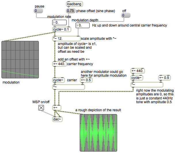
This example patch shows one cycle~ object being used as an LFO (the modulating oscillator) and another cycle~ object being used as the sound source (the carrier oscillator). The portion of the patch that’s inside the colored box shows how to use cycle~ as the modulator, using number boxes to specify the desired frequency, amplitude, and offset.


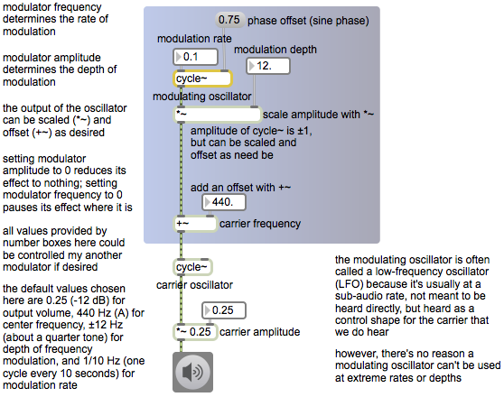
modulatorexample.maxpat

Note that the carrier oscillator’s frequency is controlled by a signal (not by typed-in argument or a Max message), which is the sum of a constant value (the offset) of 440, which you can think of as the center or base frequency, and the output of the modulating oscillator, which modifies that base frequency. The range, or depth, of that modulation is determined by the amplitude of the modulator, ± 12 in this case, so the frequency of the carrier will vary continuously between 428 Hz and 452 Hz, which is roughly ± one quarter tone variation of the central frequency. The rate of the variation is quite slow here, 0.1 Hz, meaning that a full cycle of the modulating waveform will occur once every ten seconds. Try other frequencies and amplitudes for the modulator to get an idea of the kind of frequency modulation effects that are possible.

The phase offset value of 0.75 supplied in the right inlet of the modulating cycle~ object means that when audio is turned on, that cycle~ will start 3/4 of the way through its waveform. Since its stored waveform is a cosine, starting 3/4 of the way through that cosine will cause it to start at a value of 0 instead of 1, and it will have a sine phase shift.

Music 215 assignment for Wednesday April 16, 2014

Study the examples from the previous class session.

Keep working toward your research goal. Keep refining and improving your research focus. As you do so, use the MessageBoard to report constantly on your thoughts, progress, revised plans, discoveries, etc.

Come to class prepared to do a short presentation of your progress/findings.

My understanding of the research foci and the plans of action is:

Ryan: Control of 4-color lights via DMX; study of color theory as it relates to color choices for the planned piece; study of previous ideas by composers and others relating pitch (or pitch class) to color/hue; looking into synesthesia phenomena relating color and music; pitch detection of electric bass using sigmund~; ideas for mapping detected pitches to control information for lights.

Hassan: Basics of GL programming in Jitter; applying images or videos as textures for GL objects (videoplanes and other shapes); potential methods of image distortion based on altering the shape of the textured objects; eventually, potential mapping strategies for relating music and video.

Lizzy: Research and learn the workings of certain basic delay-based audio signal processing techniques such as echos, filters, comb filtering, flanging, chorusing, etc.; record piano samples to use for testing effects; test effects with the sampled sounds, try different parameter settings, and make a library of interesting and musically useful results; consider ways that the Disklavier can contribute to this process.

Richard: Research the basics of the mathematics of probability as it applies to probabilistic decision making; research applications of that to algorithmic composition that may have been explored by others, and that you experiment with yourself; research ideas of interest in the area of machine musicianship, and see if there are connections between that and probability; consider what interface(s) might be best for multi-dimensional (orthogonal) control of parameters in a performative way.

Adjust the pitch of a comb filter

This patch demonstrates how to adjust the delay time of a comb filter to make the filter correspond to a desired fundamental pitch.


combfiltering.maxpat

The filtering formula used by the comb~ object is

y[n] = a x[n] + b x[n-(DR/1000)] + c y[n-(DR/1000)]

wherein R is the sampling rate, D is a delay time in milliseconds, x[n] is the current input sample, y[n] is the current output sample, and a, b, and c are gain scaling factors.

That formula can be shown diagrammatically like this.

In the patch we convert a MIDI-based pitch number into a frequency in Hertz, then use that to calculate the correct delay time for the filter. Using delay feedback (a past y[n] value) with feedback gain approaching 1 creates strong resonance at the comb frequency, yielding an inverted comb response pattern sort of like this,

resulting in a strong imposition of the fundamental pitch and a buzzy timbre.

Adjust pitches according to a pitch class set

One potential use of the “inlist” abstraction is to compare incoming pitches to a pitch class set. This patch uses a % 12 object to find the pitch class of an incoming pitch, then compares it with the members of a prescribed pitch class set. If it belongs to the pitch class set, it gets passed on unchanged; if it doesn’t belong to the pitch class set, it gets pushed up one semitone and tested again.


inlistdemo.maxpat

Note that this patch does point to a potential bug (a so-called “screw case”). If the pitch class set is null (the bag inside the inlist abstraction is empty), any incoming pitch would set this patch into an infinite loop and cause a stack overflow. However, we’re safe in this particular example because we have pre-loaded the pitch class set and there’s no way provided in the program to delete those numbers.

Ask if a number belongs to a set

This abstraction, which I call “inlist”, checks to see if a given number belongs to a previously-collected set of numbers. Numbers in the middle inlet are added to the set, and numbers in right inlet are deleted from the set. A ‘clear’ message in the left inlet deletes the entire set. When a number comes in the left inlet, if it belongs to the set, a 1 will be sent out the outlet, meaning “yes, it’s in the list”; if it doesn’t belong to the set, a 0 will be sent out.


inlist.maxpat

The bag object stores an unordered collection of numbers. Each time a number comes in the left inlet, we store it, then compare it with every number in the bag, storing any “yes” answer we may get. Then we send out the stored answer and reset the stored answer to “no”. (N.B. Technically, we really reset the stored answer before we send out the result, so that “inlist” will be all ready to go even if its output triggers more input in the parent patch. The answer actually gets to the final t object and is stored there for an instant while we reset the i object to 0.)