

3D CAD model of the dinghy created in SolidWorks.

Another view of the CAD model.
Development of the dinghy model

Woo sanding one of the side wall pieces of the dinghy model in the early stages of building.

Pieces of wood and other heavy objects are used to apply downward force on the two dinghy model side walls as the glue dries.

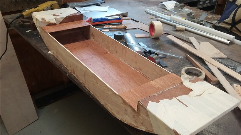
Dinghy model with completed floor and walls. The floor was bent and secured at the bow and stern using the “stitch and glue” technique which involved the use of wires to “tie” the plywood together as the glue dried. Small holes were drilled in order to thread the wires through the plywood. After the glue dried, the wires were removed.

A test fit of the dinghy model with the main hull model.

Wood pieces used to illustrate the full size dimensions of the dinghy. This was used in a discussion of seating layout.

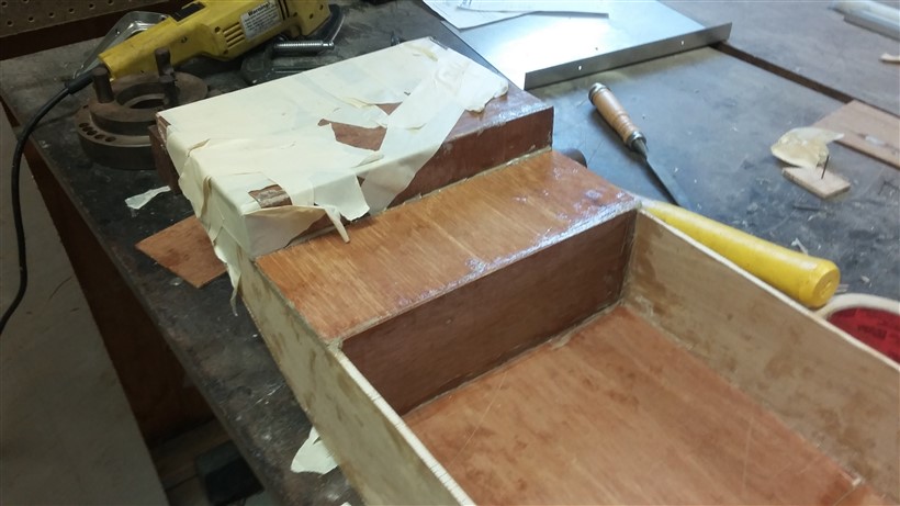
Deck pieces at both ends of the dinghy as well as small wall pieces are added to the model. Masking tape and two heavy objects are used to secure the pieces as they dry.

In addition to the masking tape and weights, clamps are used to tightly hold the deck pieces against the side walls as the glue dries.

A view of structural crossbeams that were added to the model. These crossbeams provide greater strength to the overall dinghy and will assist in supporting the loads of crew and cargo in the full size dinghy.

Another view of the crossbeams.

False floor added to the dinghy model. The floor pieces were placed on top of the crossbeams.
Small horizontal deck pieces are added to the model. Their purpose is to simulate benches on the dinghy as well as the location where the main hull central frame will rest (when the dinghy is hanging from the proa).

Another view of the bench piece.
A view of one of the two bulkhead pieces added to both sides of the model. The bulkheads join the bench pieces and the false floor.

A view of one of the strips of wood added to both ends of the dinghy model. Once sanded, the purpose of this piece is to make the application of fiberglass easier.

Close view of the sanded end piece.

View of the sanding work done on the various edges of the dinghy model.

View of the overall dinghy model without any masking tape or securing structures.

The dinghy model with the first fiberglass strips, covered with a mixture of epoxy resin and hardener.

The bottom edges of the dinghy model are sealed.
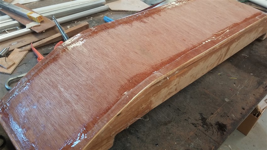
Fiberglass strips are applied to the bottom edges along with an epoxy resin/hardener mix.

A closer view of the fiberglass on one end of the dinghy model.