
Spring Quarter ’24
Week 5 Updates
Powertrain:

Finalize motor, controller, differential, chain tensioner, and chain guard mounting
Subcomponents:
- Motor Mount
- Differential Mount
- Chainguard
- Chain tensioner
- Controller
- Cooling System
- Axles
Suspension:

- Front and Rear Suspension hardpoints fixed on Chassis v6.0
- Front Roll center on ground
- Rear Roll center 0.3 in above ground
Accumulator:

Accumulator Enclosure
- Designed Exterior Walls to best fit chassis slot
- Proposed Interior Walls lined with NOMEX paper + UL94V0 Araldite (Interior Walls finalized end of this week)
- Dimensions: 27.68″(l) x 19.02″(h) x 8.42″(d)
- Submodules finalized (connected in series)
Chassis:

Relevant Edits since v5.8:
- Main Roll Hoop shortened by 5″ based on driver model repositioning
- Additional Tube members added to mounting components of Powertrain, Ergonomics, and Suspension
- Nose plane altered for mounting both ergonomics and Aerobody’s Front Wing
- Accumulator/powertrain Bulkhead reconfigured to account for new accumulator dimensions
- Simplified tube geometry for weight reduction
- Front Roll Hoop nonplanar for Driver ergonomics
Ergonomics:

- New seat CAD and head rest ready to manufacture
- Dashboard printed and installed into EVO
- PO for impact attenuator submitted
- Ergonomic Mock-Up tests completed
Electronics:

- completed Tractive System Active Light Brake System Plausibility Device Resettable Latch for AMS, IMD, and BSPD
- Now that all soldered prototypes are complete, we have begun assembling a safety system test bench.
Embedded Systems:

- Updated system schematic with Dash
- Sensor Board partially soldered
- Code updated to accept two throttle inputs of different gradients
- Digital dashboard
- Researching communication between Raspberry Pi and CAN Bus
- Configured Raspberry Pi for SPI communication
- Front wheel speed sensor
- Made PO for Hall Sensor and Tone Ring
- Created pseudo code
Week 2 Updates “Kilozott”
Suspension:
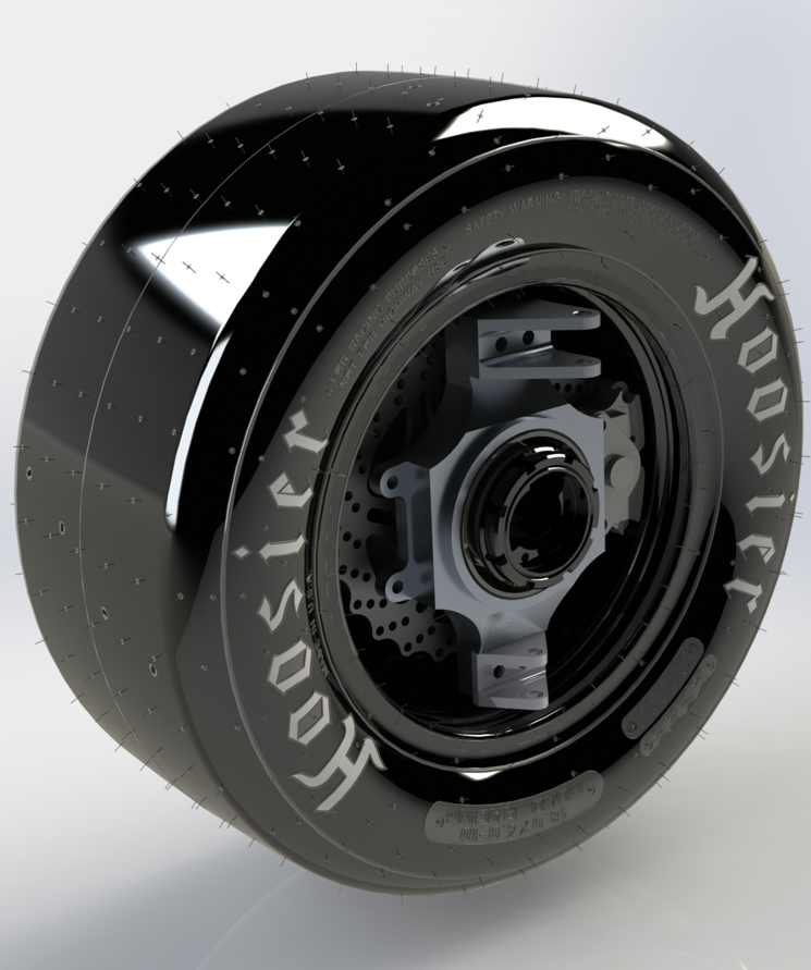
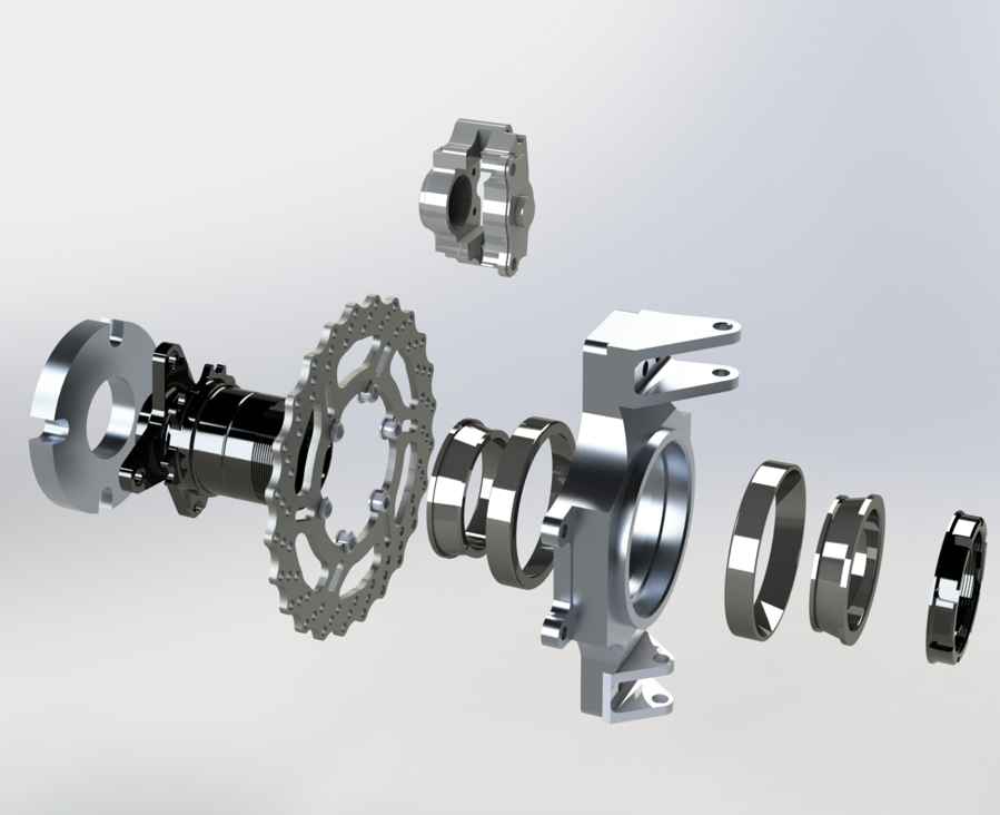
- Wheel assembly
- Brake Rotor and Caliper Assembly
- Hub, Upright, and bearings assembly
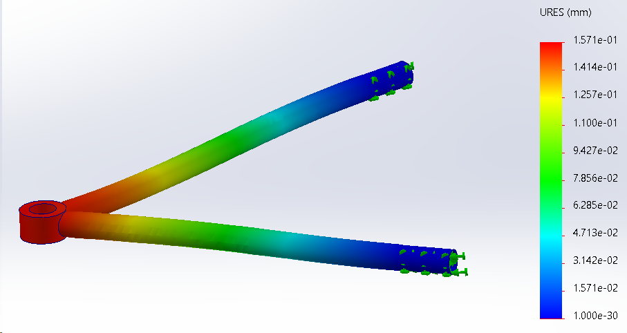
- Wishbones assembly
- Simulated using multiple potential materials for rotor
- A36 Steel, Cast Iron, 4130 Chromoly steel
- Chose 4130 Chromoly steel
- Machined rotors through SendCutSend

Accumulator:

- New accumulator submodule design:
- All 6 segments can be dropped in as “bricks”
- Has physical features to prevent reverse connections
Chassis/Aerobody:

Chassis for R.R.R (v5.8)
- Material: 4130 Chromoly Steel
- Weight: 92.8 lbs
- Alterations were done for SES verification, simplify geometry, and other subsystem components
- Colors on CAD are to denote tubes of certain wall thickness. (Red (0.095”)>Blue=Green>Yellow (0.035”))
- Aerobody model on RRR 5.7
- Completed modeling for Front and main roll hoop
- Improved the bump in the front roll hoop
- Added a skirt and cut holes where needed for aerodynamics
- Cut out holes for front suspension
- Completed modeling for Front and main roll hoop

Embedded

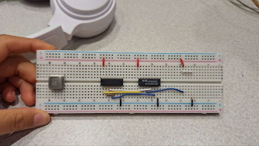
Precharge Circuit
- Ruggedized using soldered breadboards and molex headers
- Board was wired to the motor test bench
- Precharge constants were tuned to the battery and resistor
- With a 60V battery and 400 Ohm resistor, we found that a reliable precharge curve was charging to 91% battery voltage in 2.5 seconds (±0.3 seconds)
Winter Quarter ’24
Week 4 Updates
Suspension:

- Determined cast iron rotors were too expensive after receiving multiple quotes
- Finalized the thermal analysis and simulations to verify the brake rotor material (Hot-rolled A36 mild steel)
- PO form sent for RCV front and rear Hub components and for Brake Caliper
- Scanned centerpiece for rim
Powertrain:

- Ordered Motor and Motor Controller
- Design for Differential mounting and motor mounting completed
Chassis-Aero Body:
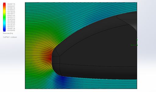
- Remodeled aerobody to support SW Flow simulations
- Remodeled nose-cone to reduce drag
- Successfully ran SW Flow simulations with previously used conditions
- Obtained a 14% drag reduction
Embedded Systems:

- APPS/Brake Pedal Plausibility Check implemented
- Vehicle state diagram corrected
- Key switch adapted to pushbutton
- Voltage to frequency IC breadboarded
Electrical:

Accelerator Pedal Position Sensor (A):
- Assembled circuit
- Logic tested and verified
- Wrong MOSFET transistor identified
Accelerator Pedal Position Sensor (B):
- Assembled Logic section of circuit
- Logic tested and verified

Insulation Monitoring Device and Crystal Oscillator:
- Assembled circuit
- AND gate verified
- Flipflop/latch troubleshot
- Solution found: SR latch
Fall Quarter ’23
Week 10 Updates
Suspension: Done various FEA testing on parts:
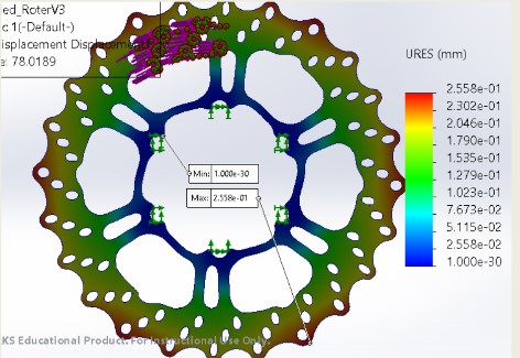
- FEA on the brake rotor when decelerating by 2g. (According to Brian’s simulation conditions)
- Applied a 2452 N force to the area where the brake pad would clamp the disc
- FEA on the brake rotor when decelerating by 2g. (According to Brian’s simulation conditions)
- Applied a 2452 N force to the area where the brake pad would clamp the disc
Powertrain: Remodeled Motor Mount

- Reduced Motor Mount height from 17.5 inches to 12.6 inches
- Added additional bolt holes – Outer ring of bolt holes for ME1507 (Increased width by ⅝ of an inch)
- Results: Motor Mount assembly’s mass (without the motor) reduced from 16.6lbs to 10.5lbs
- Determined the distance between the center of each sprocket to be 13.6 inches
- Results in the driven sprocket having:
- 4 teeth fully engaged, 2 teeth partially engaged
Chassis: Remodeled Main Chassis and Done Various FEA

- Front roll hoop aerobody complete
- Created new nose cone that would adhere to surface better
- Nose cone dimensions:
- 25” long
- Base is 16” x 18”
- Thickness of 0.10”
- Main roll hoop shortened in width by 6” (39” – 33”)
- Rear Impact member deleted, accumulator section lengthened to compensate for accumulator/powertrain packaging
- Firewall angled to 55 degrees (prev. 30) to account for seat ergo
- Main Hoop braces lowered by 5” (FSAE Min) to account for CG
- Removed redundant members on Front Bulkhead Triangulation (~1.5 kg)
Embedded: Completed Schematics and prototyping
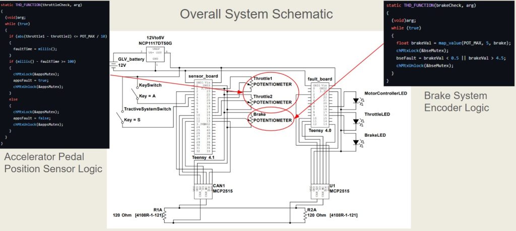
- Completed schematic
- Finished safety circuits schematics and physical prototype
- Accelerator Pedal Position Sensor
- Brake System Encoder
- Ready to Drive/Ready to Drive Sound logic