

SolidWorks stress simulation on a CAD model of the proa. The model was created in SolidWorks. This simulation in particular involved studying how large forces on the Ama effect the crossbeam structure. Such forces on the Ama could be created by waves and water forcing the Ama to not only displace upwards but also twist. The areas of interest are the portions of the crossbeams that join the main hull. As can be seen by the red coloring, the largest stresses occur where the crossbeams meet the main hull which is expected. An extremely strong joint area is critical for the final proa. In addition to the analysis of the joint areas, the simulation illustrates that this crossbeam design has a reasonable stress distribution, making the design itself more promising.
Images appear in chronological order
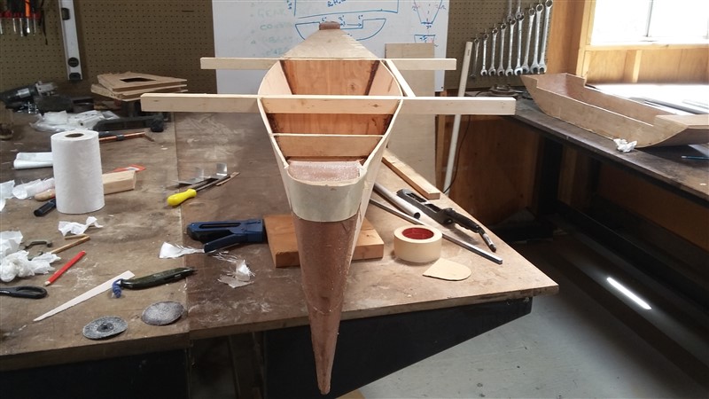
Early work on the model main hull.

Front view of the model main hull, ama, and crossbeams in the Orthogonal shop. Pictured is professor Simon Penny of the UC Irvine Claire Trevor School of the Arts.

View of the main hull and ama with a focus on the ama and ama crossbeam layout.


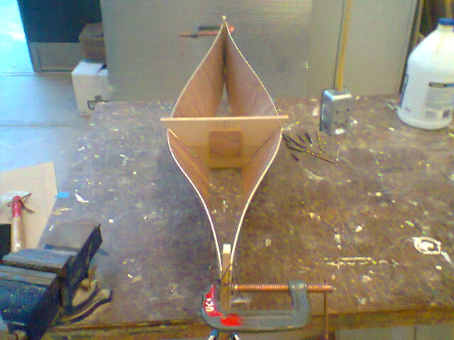
Ama model after further development
The main hull with rounded bow and stern pieces. A deck pieces is also visible.


The fore and aft deck pieces are visible.

View of the ama model.

Woo sanding the main hull model.

View of the Vaka, Ama, Dinghy, masts and control mechanisms, rudder and Bidirectional foil.