This Blog is part 1 of a series of “Component Introductions” from Embedded System subteam of our FSAE Electric, with the goal of introducing and explaining the computer control modules used in the vehicle. This blog can also be read on the Electric Teams’ “The Track” webpage, found here.
What is the Driver Input Module?
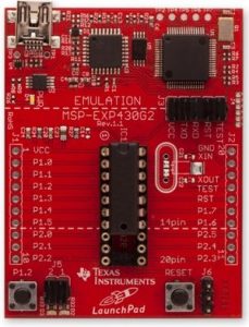
The Driver Input Module (DIM) is a Texas Instruments MSP430G2ET (implemented with a G2553 integrated circuit) Micro-controller with the requirements of handling driver input of Lithium, UC Irvine’s 2019 FSAE Electric Racecar competing in Lincoln, Nebraska. The driver input includes two independent Accelerator Pedal Position Sensors (APPS), one Brake System Encoder (BSE), and one Steering Angle Position Sensor (SAPS). These inputs are processed by the DIM then forwarded to the Central Control Module (CCM) via CAN (Controller Area Network) with the use of a MCP2515/2551 CAN controller and transceiver.
Context of the DIM:

The figure to the right describes the context of the DIM. The driver input sensors (APPS, BSE, and SAPS) are analog potentiometers ranging from 0V-5V connected to the Analog-to-Digital Converter (ADC) of the DIM. The DIM utilizes this input data to check for faults in the system on a software level. Once the driver initiates the start sequence (applying brakes and pressing the start button) and no faults occur, these values are transmitted to the CCM of the racecar via the CANBus. Since the DIM micro-controller has no native CAN support, a MCP2515 CAN controller is connected via Serial Peripheral Interface (SPI) and a MCP2551 CAN transceiver is the interface between the aforementioned CAN controller and the physical CAN bus.
Description of the Faults:
“Faults” were previously mentioned and are critical to the design of the DIM for a tech-ready racecar. Faults can arise if the accelerator (depressed at >20%) and brake pedal are actuated at the same time, if there is a floating input voltage in either sensor, or if there is different APPS voltages between the two independent inputs. These faults are defined as a “plausibility” by the FSAE rulebook, and must be accounted for in our Failure Mode Effect Analysis (FMEA). If a plausibility occurs, the DIM will send throttle values of zero until the fault is cleared.
The DIM is essential for Lithium to be safe and tech-ready for final competition in Lincoln, Nebraska. This system is used to detect faults to prevent the racecar from transmitting incorrect pedal values for safe operation. Furthermore, the DIM provides hands-on experience with a microcontroller and interfacing it with CAN Bus to integrate it in a functional racecar for UC Irvine undergraduate Computer Engineers. DIM has been in development since the beginning of Fall 2018 quarter and is expected to be integration ready by February of 2019.