AER: Developing a Comfortable Driver Fit with an Ergonomics Jig

Written by: Anteater Electric Racing Media

To produce results in the Formula SAE Competition, the ergonomics of the driver are just as important as the performance. Our 2020 FSAE Electric Racecar, named Ampeater, holds many components into a very small chassis, therefore making ergonomics critical to the operation of the vehicle. To resolve this problem, the development of an ergo jig was needed to research the ideal position of the driver inside the chassis so all mechanical components could be placed accordingly and taken to the Cal Club SCCA autocross event for feedback…

Click here to read the full blog on the Anteater Electric Racing Website!

Keeping it Cool: AFR’s Cooling System Upgrades for ’20

by Dillon Smith

The Engine Development team at Anteater Formula Racing is hard at work on developing cooling upgrades for this year’s car.

The Formula SAE competition demands the best from every system, but one of the biggest challenges is keeping the engine cool during the Endurance event.

This year, Wraith suffered from a seized engine during Endurance at Lincoln. This was due in part to the engine overheating during competition. The maximum safe operating temperature for our engine is 200 degrees Fahrenheit, but data taken from the ECU after the breakdown showed that coolant temps reached over 250 degrees after sitting for several minutes during the mandatory driver change, which starved the radiator of cool air.

The engine team has been running tests at UCI’s Vehicle Performance Engineering Lab to determine the specific cause of failure since the summer and are developing upgrades to keep Jinx cool. By measuring the water flow rates through the running engine at various RPMs and measuring the temperature drop from the radiator inlet and outlet, we’ve been able to measure Wraith’s overall cooling ability. Our calculations show that the previous design is insufficient for our needs, so we’re undergoing a full redesign of the cooling system to meet our current requirements. So far this year, our focus has been on reliability so that we can push the car harder and perform better in competition with less issues.

Figure 1  AFR’s Engine Development Sub-team runs tests on last year’s cooling system.
Want to support our developments and our 2020 car? Consider donating to our ZotFunder campaign here, running through 12/1/19.

How a standard water-cooled system works:

As the engine runs, it generates large amounts of heat.  In order to keep the engine temperature at 200 degrees, the excess heat is absorbed using a water-cooling system that pumps cool water through the engine block. The hot water is then passed through a thermostat which opens once the temperature of the water reaches 190 degrees. To avoid cavitation, or the creation of low-pressure pockets that interrupt water flow, the hot water is then sent to a swirl pot, which allows any steam in the system to condense back into liquid. This condensed hot water is then sent through the radiator, where heat is removed through convection, and then is sent back into the engine using a pump.

Figure 2 Block diagram for the Jinx cooling system.

The radiator performs most of our cooling by passing the engine coolant through an exposed fin setup that allows the passing air to absorb heat from the system. Increasing the temperature drop across the radiator allows our engine to run cooler and avoid overheating.

To do this:

  1. We’ll install a larger radiator as well as more powerful cooling fans to improve the airflow to the coolant.
  2. We’ll install an upgraded water pump to increase coolant mass flow through the system.
  3. We’re working with our Aerodynamics team to design a custom sidepod to maximize the amount of air that is directed to our radiator (Figure 3).

Figure 3 CAD design of Jinx cooling system.

We expect to have Jinx up and running in early 2020, stay tuned!

Dillon Smith is a fourth-year mechanical engineer on AFR’s Engine Development sub-team, which is led by Tristan Cortez and also includes Mohammed Azeem, Daniel Martinez, Mason Socha, Sangghara Kusumo, Edward Han and Dustin Ngo.

Anteater Formula Racing Chief Engineer McMurry Wins IMSA Championship

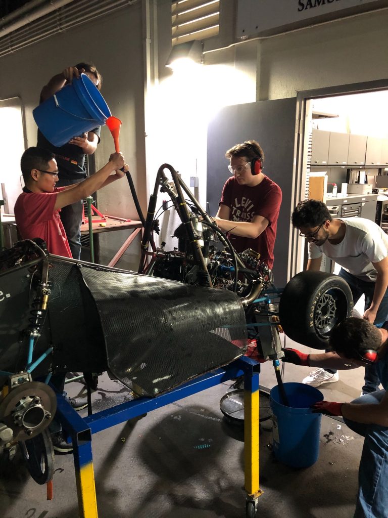
Matt McMurry (left) with co-driver Dalton Kellett (right) and the #52 PR1-Mathiasen Motorsports Team

Braselton, GA. — At the Petit Le Mans on Saturday, October 12, Anteater Formula Racing Chief Engineer Matt McMurry sealed his first Driver’s Championship in the IMSA WeatherTech Sports Car Championship’s LMP2 class. He also earned his sixth class win of 2019.

McMurry, Aerospace Engineering ’20, currently leads the development of Anteater Racing’s entry for the 2020 Formula SAE California competition next June.

From the International Motor Sports Association (IMSA):

McMurry, PR1 Mathiasen Motorsports Win LMP2 Race and Championship

The Le Mans Prototype 2 (LMP2) class was decided by the halfway point of Saturday’s 10-hour race. By just taking the green flag, the No. 52 PR1 Mathiasen Motorsports ORECA LMP2 wrapped up the team championship, with driver Matt McMurry clinching the driver’s title.

The No. 38 Performance Tech Motorsports ORECA won the LMP2 pole in qualifying on Friday but was eliminated less than 90 minutes into the race. Cameron Cassels slowed in the esses to let the No. 6 Acura Team Penske DPi go past. But the trailing No. 7 Acura Team Penske DPi ran into the rear of the No. 38, sending it into the Turn 4 barrier and bringing out the first full-course caution of the day.

That left the No. 52 driven by McMurry, Dalton Kellett and Gabriel Aubry alone in class on track. Just past the halfway point, however, smoke erupted from the rear of the car, and it headed to the paddock and didn’t return.

“I wish we could have raced into the night to see how the track is and how the lead would hold,” Aubry said. “We had a good car. I think something happened on the rear suspension and took us out of the race. The track is tough on the car, but that’s how it goes.”

The victory was the sixth in a row to close the LMP2 season for the No. 52. It propelled McMurry, the 21-year-old from Phoenix, to the first major championship of his young racing career.

“It’s amazing,” McMurry said. “I’ve been watching IMSA my whole life. My dad drove in LMP2 and P1 for years, and to be the champion is pretty special.

“The team did great all year, I couldn’t have done it without them. They performed pretty flawlessly all year. There were a couple of unfortunate things that happened, but it was nothing the team could have done to prevent it. The team, all the pit stops were perfect, the suspension and setup were almost always spot on as soon as we pulled it off the trailer.

“It’s special, and I’m glad I did it with PR1, and with Dalton and Gabby.”


Component Introductions – Driver Input Module of the Lithium EV

This Blog is part 1 of a series of “Component Introductions” from Embedded System subteam of our FSAE Electric, with the goal of introducing and explaining the computer control modules used in the vehicle. This blog can also be read on the Electric Teams’ “The Track” webpage, found here.

The Texas Instruments MSP430 Launch Pad used for the DIM


What is the Driver Input Module?

The Driver Input Module (DIM) is a Texas Instruments MSP430G2ET (implemented with a G2553 integrated circuit) Micro-controller with the requirements of handling driver input of Lithium, UC Irvine’s 2019 FSAE Electric Racecar competing in Lincoln, Nebraska. The driver input includes two independent Accelerator Pedal Position Sensors (APPS), one Brake System Encoder (BSE), and one Steering Angle Position Sensor (SAPS). These inputs are processed by the DIM then forwarded to the Central Control Module (CCM) via CAN (Controller Area Network) with the use of a MCP2515/2551 CAN controller and transceiver.

Context of the DIM:

Context Diagram of the DIM

The figure to the right describes the context of the DIM. The driver input sensors (APPS, BSE, and SAPS) are analog potentiometers ranging from 0V-5V connected to the Analog-to-Digital Converter (ADC) of the DIM. The DIM utilizes this input data to check for faults in the system on a software level. Once the driver initiates the start sequence (applying brakes and pressing the start button) and no faults occur, these values are transmitted to the CCM of the racecar via the CANBus. Since the DIM micro-controller has no native CAN support, a MCP2515 CAN controller is connected via Serial Peripheral Interface (SPI) and a MCP2551 CAN transceiver is the interface between the aforementioned CAN controller and the physical CAN bus.


Description of the Faults:

“Faults” were previously mentioned and are critical to the design of the DIM for a tech-ready racecar. Faults can arise if the accelerator (depressed at >20%) and brake pedal are actuated at the same time, if there is a floating input voltage in either sensor, or if there is different APPS voltages between the two independent inputs. These faults are defined as a “plausibility” by the FSAE rulebook, and must be accounted for in our Failure Mode Effect Analysis (FMEA). If a plausibility occurs, the DIM will send throttle values of zero until the fault is cleared.


The DIM is essential for Lithium to be safe and tech-ready for final competition in Lincoln, Nebraska. This system is used to detect faults to prevent the racecar from transmitting incorrect pedal values for safe operation. Furthermore, the DIM provides hands-on experience with a microcontroller and interfacing it with CAN Bus to integrate it in a functional racecar for UC Irvine undergraduate Computer Engineers. DIM has been in development since the beginning of Fall 2018 quarter and is expected to be integration ready by February of 2019.