Abstraction for quad panning using x,y coordinates

Image

There are several standard and speaker configurations for 2-dimensional surround sound panning, such as quadraphonic (four speakers in a square or rectangular placement) and the 5.1 or 7.1 THX cinema surround specifications. There are also sound distribution encoding techniques that work for a variety of speaker configurations, such as the Ambisonics panning description, and there are processing techniques such as head-related transfer functions (HRTF) filtering.

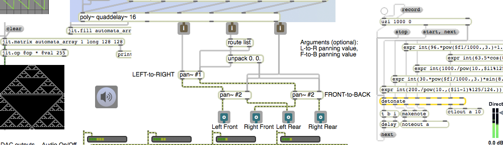
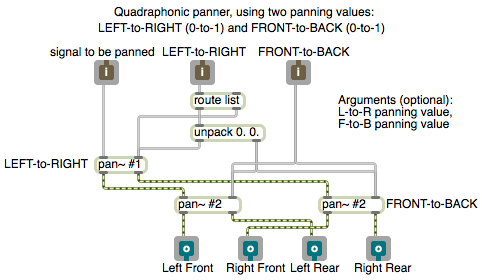
This and the next few examples will show simple algorithms for intensity panning with a rectangular quadraphonic speaker configuration.

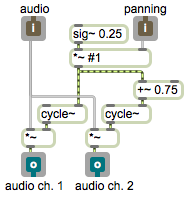
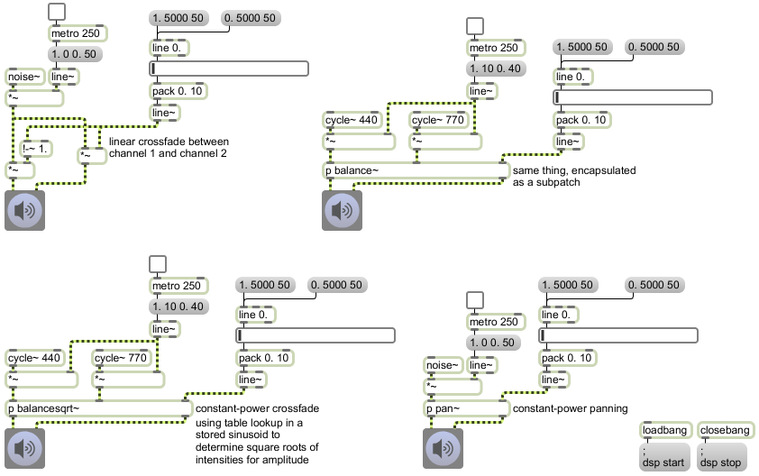
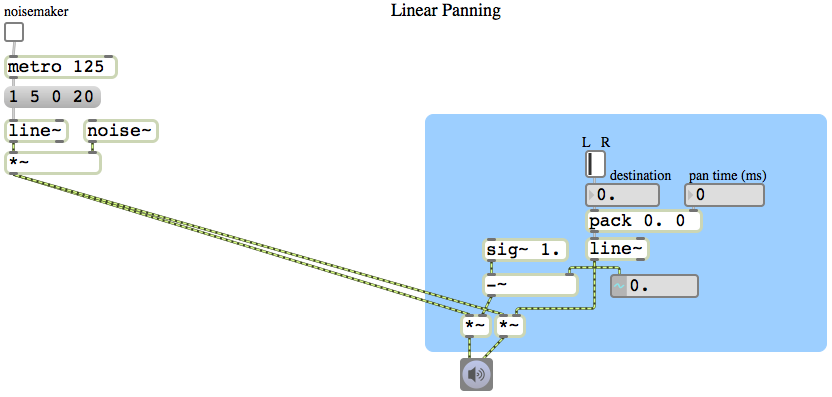
One way to implement two-dimensional panning is to specify the sound’s virtual location as a x,y coordinate point on a rectangular plane representing the floor of the room, with a speaker at each corner of the plane. The x value can be used to represent the left-right panning (0 to 1, going from left to right) and the y value represents the front-back panning (0 to 1, going from front to back). For some purposes, simple linear panning might suffice (or even be found to be preferable). I usually prefer to use a constant intensity panning algorithm. So I use the pan~ abstraction to calculate the amplitudes that will provide the left-to-right panning illusion, and then I use two other pan~ objects to pan each of those gains (the left and right amplitudes) from front to back.

This patch is an abstraction that enacts that plan. (It requires that the pan~ abstraction be somewhere in the Max file search path.) You can use this to pan any signal to four speakers in a rectangular quadraphonic layout. It takes a signal in its left inlet, an x coordinate in its second inlet, and a y coordinate in its right inlet. Similarly to the pan~ abstraction, it allows the panning coordinates to be specified as initial arguments, floats in the 2nd and 3rd inlets, or as signals.

Abstraction for constant-intensity stereo panning

Image

For the basics of intensity panning for stereo sound in MSP, you might want to review Example 12 on linear amplitude panning, and Example 13 and Example 14 on constant power panning, from the 2012 Interactive Arts Programming class.


This patch is a very useful abstraction for constant-intensity stereo panning of sound. It’s identical to Example 43 from the 2009 Interactive Arts Programming class, so you can read a description of it there.


Notice how this abstraction allows the user to specify the panning position in any one of three ways: as a typed-in value in the parent patch to set an initial value, as a float to change instantly to a new position, or as a signal to change continuously and smoothly from one value to another.


Save this patch with the name “pan~”. It’s needed for the next two examples.


Constant power panning using table lookup

Image


In the previous example we used the square root of the desired intensity for each speaker to calculate the amplitude of each speaker. However, square root calculations are somewhat computationally intensive, and it would be nice if we could somehow avoid having to perform two such calculations for every single audio sample. As it happens, the sum of the squares of sine and cosine functions also equals 1. So, instead of using the square roots of numbers from 0 to 1 (and their complements) to calculate the amplitude for each speaker, we can just look up the sine and cosine as an angle goes from 0 to π/2 (the first quarter of the cosine and sine functions).

In this patch, therefore, we scale the panning value down to a range from 0 to 0.25 and we use that as the phase offset in a 0 Hz cycle~ object. As the panning value moves from 0 to 1, the left speaker’s amplitude is looked up in the first quarter of a cosine function and the right speaker’s amplitude is looked up in the first quarter of a sine function (by adding an additional 0.75 to the scaled phase offset). The resulting effect is just the same as if we performed the square root calculation, but is less computationally expensive.

In most cases this is the preferred method of constant-power intensity panning between stereo speakers. It’s so generally useful that it’s worthwhile to implement it and save it as an abstraction, for use as a subpatch in any MSP program for which stereo panning is required. An abstraction version of this method is demonstrated in Example 43 from the 2009 class.

Constant power panning using square root of intensity

Image


The intensity of sound is proportional to the square of its amplitude. So if we want to have a linear change in intensity as we go from 0 to 1 or 1 to 0, we need to use the square root of that linear change to calculate the amplitude. This example patch is exactly like the previous example, except that we consider the linearly changing signal from line~ to be the intensity rather than the amplitude, and we take the square root of that value to obtain the actual amplitude for each speaker. By this method, when the sound is panned in the center between the two speakers, instead of the amplitude of each speaker being 0.5, it will be the square root of 0.5, which is 0.707 (which is an increase of 3 dB compared to 0.5). This compensates for, and effectively eliminates, the undesirable ‘hole-in-the-middle’ effect discussed in the previous example.

Linear amplitude panning

Image


The simplest and most common way to localize a sound in a stereo field is to vary the relative intensity between the two speakers. To make a sound seem to move from one side to the other, for example, you can start with the level of one speaker set to 1 and the other speaker set to 0, then gradually turn one down to 0 as you bring the other up to 1. This patch demonstrates a direct linear pan from one speaker to the other.

The left side of the patch is just a noisemaker, to give us a sound to pan. It creates 8 short bursts of white noise per second. The right side of the patch performs the linear intensity pan. It uses a line~ object to go from 0 to 1 (or 1 to 0) in a given amount of time. (The L-R switch to go from 0 to 1 or 1 to 0 is just a slider object set to have only two possible values.) The value of the line~ object is used directly to control the amplitude of the right speaker, and it is subtracted from a constant signal of 1 to create the opposite amplitude (i.e., 1 minus the amplitude of the right speaker) for the left speaker.

When the panning is at the midway point, both speakers will have an amplitude setting of 0.5 (i.e. -6 dB); but two speakers at -6 dB generally does not produce the same perceived loudness as one speaker at 0 dB. Therefore, this sort of linear amplitude panning creates a slightly lower perceived intensity in the middle than when the sound is panned fully to one side or the other. Because the intensity is lower in the middle, the impression it gives it that the sound is moving slightly farther away from the listener as it moves toward the center location. This is considered to be undesirable in most cases, so panning algorithms often compensate for this effect by increasing the amplitude by about 3 dB as the panning moves to the center position, as demonstrated in the next example.