Routing MIDI to other applications

Image

The easiest way to establish MIDI connection between Max and other applications on the same computer is via the “virtual” MIDI ports Max provides. Max creates two virtual input ports and two virtual output ports that can be accessed by other MIDI applications. (You can see those virtual ports listed in Max’s MIDI Setup, by choosing MIDI Setup… from the Options menu.)

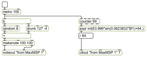
This example shows how one can generate MIDI information in Max and send it to another application. Here note information and controller information is being sent to the virtual port “from MaxMSP 1”. Any application that’s set to receive MIDI input from that virtual port will get the data that Max is transmitting. In this case Max is generating a cloud of random notes and is also moving the volume up and down in a sinusoidal fashion every 100 notes.

Using matrix~ for audio routing and mixing

Image

The matrix~ object is an audio mixer/router that can be configured with any number of inlets and outlets. The arguments specify the number of audio inlets, the number of audio outlets (there’s always one additional outlet on the right), and the initial gain for the connections of inlets to outlets. Each inlet is potentially connectable to each outlet with a unique gain setting. The gain of the connections is changed by sending messages in the left inlet.

The messages in the left inlet of matrix~ specify an inlet number (numbered starting from 0), an outlet number, a gain factor for scaling the amplitude of that connection, and a ramp time in milliseconds to arrive at that amplitude. You can send as many such messages as needed to establish all the desired connections.

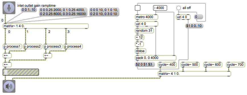
The patch on the left shows how matrix~ can be used to route a signal to multiple destinations. The first message connects inlet 0 to outlet 0 with a gain factor of 1 and a ramp time of 10 milliseconds, which is to say that it quickly opens the first outlet. The next message sets all four outlets to an amplitude of 0.25, but assigns a different fade time to each outlet, which shows that matrix~ can be used as a mixer as well as a simple router. The third message quickly turns off all four outlets (turns them all to 0 amplitude in 10 ms).

This method of sending a message for each possible connection may seem a bit cumbersome, but in fact it’s about the most efficient way to control a large matrix (a virtual patchbay) of possible connections. With some clever message management, you can control or automate a great many constantly-changing connections. The patch on the right automates a constantly-changing mix of four sound sources.

Every four seconds (or whatever time interval you choose) the metro bangs an uzi object which outputs four messages (numbers from 0 to 3 out its right outlet, and four bangs out its left outlet), which in turn trigger four messages to matrix~. Each bang from uzi chooses a random amplitude from -12 dB to -42 dB, packs it with a connection number and a transition time, and formats that as a connection message for matrix~.

Routing audio data flow

Image


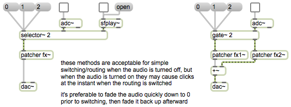
The selector~ and gate~ objects serve the same function for audio signals as the switch and gate objects do for Max messages. The selector~ object chooses one signal inlet to pass to its outlet. The gate~ object chooses one outlet out of which to pass its incoming signal.

Because the selector~ and gate~ objects make their changes instantly, they might cause a click to occur in the audio signal. For this reason, they’re best used only for situations when there’s no signal passing through them or when the signal is at 0. In general, to make such a switch you’ll want to fade the audio signal quickly down to 0 before making the switch, then fade it back up immediately afterward.

Routing MIDI data flow

Image


Managing the flow of data in a program is a common issue. Often you’ll want to receive data from different sources, or send it to different destinations.

To receive data from one of multiple sources, the switch object can be used to pass out the messages that come in just one (and only one) of its inlets at a time, ignoring any messages that may be coming in other inlets in the meantime. The leftmost inlet is the control inlet, used to determine which of the other inlets will be “open” and will pass its messages out the outlet. 0 in the control inlet means all inlets are closed; 1 means that the 1st of the other inlets is “open”, and so on.

The gate object is a counterpart of switch. Its left inlet is the control inlet, just as with switch. The number received in the left inlet determines which outlet will be “open”, and gate will pass messages from its right inlet to that open outlet.

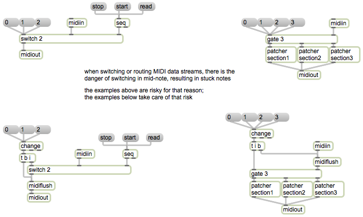
These patches demonstrate how switch and gate can be used to manage the flow of MIDI data in a patch. In the upper left, the switch object allows us to choose which source of MIDI data we want to pay attention to — the data coming from the midiin object or the data coming from the seq object. In the upper right, a gate object allows us to direct the data from midiin to one of three different subpatches. This potentially allows a single program to process incoming MIDI data in one of several different ways (in different subprograms).

The principle, in each case, is for a single program to be able to do different things, to process information differently, at the flip of a switch.

Notice one little potential problem. If we cut off a flow of MIDI messages, there is always the chance that we might interrupt the flow of data between a note-on message and its corresponding note-off message, resulting in a stuck note. The patches in the lower part of the example demonstrate reasonable precautions to protect against such stuck notes occurring.

The midiflush object is designed to turn off held notes. It keeps track of each MIDI note-on message that passes through it until it receives a corresponding note-off message. Thus, it always has in its memory all the held notes that have not yet been turned off. When it receives a bang, it sends out a note-off message for any remaining note-ons.

In each of the two lower patches, we check to see when the control inlet of the switch or gate object is changed, by using the change object. (There will only be output from the change object when its input actually changes.) When it does change, we send a bang to midiflush to turn off any notes that are held at the moment. Notice that in the patch on the right it’s important to send the bang to midiflush before switching the outlet of gate, to make sure that the note-offs go out the proper outlet.