Assignment for March 5, 2015

To begin familiarizing yourself with the way that Jitter objects use Open GL for 3D animation, read as many as you can of the Jitter Tutorials numbered 30-34.

Study the following examples of Jitter objects that enable 3D animation with Open GL.

Create a sphere in Open GL
Display a video on a shape in OpenGL
Apply a texture to a shape in OpenGL
Display a video on a plane in OpenGL
Alphablend a videoplane in OpenGL

You can also take a look at the Max Documentation reference manual listing of the attributes and messages that are common to all the Open GL objects in Jitter.

Jitter object overview

Did you know that there’s a patch that comes with Max that provides a helpful listing of just about every Jitter object categorized by the type of thing the object can do, a terse description of what each does, and a way to click to see the help file or reference page for each object?

/Users/Shared/Max 7/Examples/jitter-examples/overview/jitter.overview.maxpat

Assignment for March 3, 2015

In class I’ll introduce the basics of using the JavaScript programming language within Max.

In preparation, read this introduction to JavaScript in Max, and then study this set of three small JavaScript programs. Download and save the six files in that directory. The files are meant to be studied in progressive order: 1) bang2x.maxpat, 2) number1x.maxpat, 3) numbearray.maxpat. Within each patch double-click on the js object to open the script it contains. Study each script till you understand how it works. (Ask questions about anything you don’t understand!)

There’s quite a bit of JavaScript documentation within the Max application’s Max Documentation, which you can also read in the online version. In that documentation, read the Introduction, and Basic Techniques.

You can look up anything about features of the JavaScript language in the official JavaScript reference manual.

JavaScript in Max

The js object allows you to write and run a JavaScript program inside Max.

JavaScript was developed as a language for writing programs, called scripts, that would run within Web pages. For that reason, most basic tutorials you might read about JavaScript give you a lot of information about how to write programs that do useful things in Web pages, but those tutorials aren’t especially relevant to Max. This post is intended to give you some background information that will get you started writing JavaScript programs within Max.

JavaScript effectively has two parts, a generic programming language, called core JavaScript, and a part that does Web-specific tasks, called client-side JavaScript. The Max js object runs the core programming language, but disregards all the client-side part, which is specific to Web pages, and therefore is irrelevant in Max. The Max version of JavaScript also includes some additional Max-specific features, having to do with inlets, outlets, and Max messages, which would be irrelevant in a Web page.

When you create a js object in a Max patcher window, you can Command-double-click on it (Control-double-click in Windows) to open up a text window for you to type your JavaScript program. By default, the js object will have one inlet and one outlet. If you want more than that—say, two outlets, for example—you can just type this line at the beginning of your text file:

outlets = 2;

The “=” sign means “is”. So in this case, the statement means, “The number of outlets is 2.” Every command in a JavaScript program should end with a semicolon “;”.

What do I want my js object to do? Let’s suppose I’d like it to send a greeting message out its outlet when it gets the message ‘greeting’ in its inlet. (Admittedly that’s a stupid task that you’d probably never want to do in Max, but bear with me for the sake of this example.) In order for your js object to understand the message ‘greeting’ you need to write what’s called a function that will respond to that message. You’d have to type something like this:

function greeting()
{
    outlet(0, "Hello there!");
}

The word ‘function’ creates a function, the word ‘greeting’ gives it a name that corresponds to the message that will trigger it, the empty parentheses (), which should follow the function name without any space, mean that the ‘greeting’ message won’t have any additional arguments, and the curly brackets {} enclose the commands that we want to happen when the message ‘greeting’ is received. The ‘greeting’ function has only one command, which says, “Out of the first outlet, send the message “Hello there!”. ‘outlet’ is a built-in function that already exists in js, which performs the task of sending a message out the designated outlet. It has two arguments: the outlet number, and the message to be sent out. Outlets, like most things in computer programs, are numbered starting at 0, so outlet 0 is the first outlet. As usual, the command ends with a semicolon.

That’s a complete (if not very sophisticated) JavaScript script. You would just save the text file with a .js filename extension somewhere in the Max file search path, then type your filename as an argument in the js object, and it will look for and load your script the next time the patch is loaded.

Now let’s try a script thats just a bit more practical. Let’s write a script that will output the square of whatever floating-point number you send in. There’s a built-in function name you should use for float messages, called ‘msg_float’.

function msg_float(f)
{
    outlet(0, f*f);
}

This script is not very different from the first example. In this case, though, the parentheses contain an argument, designated by the variable f, that will contain the whatever number you send in the inlet. So in our outlet function, we send the product of f times f out of the first outlet. You would just save this script in a file called squared.js (or whatever name you prefer), and load that file into a js object by typing it as an argument in the object box.

This mini-tutorial is just the tip of the iceberg of possibilities, of course. You can learn a few more basics by studying this additional set of three small JavaScript programs. Download and save the six files in that directory. The files are meant to be studied in progressive order: 1) bang2x.maxpat, 2) number1x.maxpat, 3) numbearray.maxpat. Within each patch, double-click on the js object to open the script it contains.

You can also look up anything you don’t know in the official JavaScript reference manual.

Audio in RAM — buffer~ and related objects

Preloading sound into random-access memory (RAM)—as opposed to reading it off of a hard disk—allows you more easily to access any point in the sound file instantaneously, read backwards as well as forwards, access different points in the sound simultaneously, etc. When reading from disk, you usually need to give the computer a tiny bit of advance notice to preload some of the sound into memory before you use it; that why, if you have the RAM available, it often makes most sense just to preload whatever sound you’ll need into memory.

The buffer~ object establishes a named location in RAM in which you can store audio data. You can preload a sound file (or a portion of a sound file) into that buffer~ with the message ‘read’ or ‘replace’. Other MSP objects can then refer to that memory location  by name, and can use the data in various ways.

You can find examples of different ways to use the sound data in a buffer~ in the following examples from previous classes:
Examples 15-21 from winter quarter 2012
Examples 6-13 from spring quarter 2012

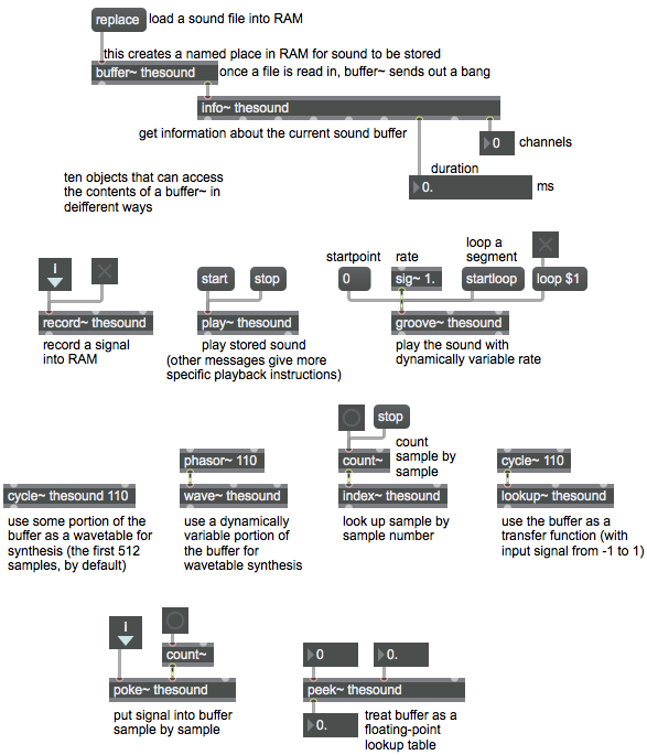
The patch below doesn’t really do much of anything, but it gathers together many (not all!) of the objects that can refer to a buffer~. You can Option-click (Alt-click on Windows) on each object to learn more about how it works.

ways to use audio data in a buffer~


Assignment for February 26, 2015

In preparation for a discussion of intensity-based panning,
a) read the Wikipedia entry on panning,
b) take a look at these three consecutive examples:
Linear amplitude panning
Constant power panning using square root of intensity
Constant power panning using table lookup
and
c) read MSP Panning Tutorial 1: Simple panning.
(The link is to the web version of the documentation; you can also read it in the Max Documentation within the Max application, which will allow you to try out the tutorial patch, as well. If the last part, about “speaker-to-speaker crossfade” makes your brain explode, you can skip that part.)

Take a look at this abstraction for constant-intensity panning, which you might find useful in your own work.

Write subtitles onto a video

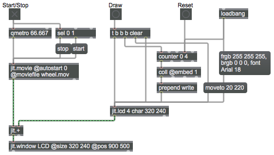
One way to combine text and video is to write text in jit.lcd as demonstrated in the example “Draw shapes and text“, then composite that matrix with a video matrix. In this example we’ll write white text on a black background in jit.lcd and simply add that matrix to a video matrix.

trigger a sequence of subtitles

On the left side of the patch I load in a small test video that comes with Max, which I happen to know has dimensions 320×240, no audio, and a frame rate of 15 fps. When you turn on the toggle labeled “Start/Stop”, it starts the video and begins triggering output 15 times per second.

The right side of the patch will use a counter to look up lines of text in the coll, and will use that text as the content of a ‘write’ message to jit.lcd. The loadbang object initially sets the foreground color (pen color) of jit.lcd to white and the background color to black, and sets the desired font type and size. It also bangs the fourth inlet of the counter, causing it to send out its minimum value, which is 0. If you double-click on the coll object, you’ll see that it contains four lines of text, numbered 1 through 4, but the coll contains nothing at index 0, so nothing will get sent out of the coll in response to an input of 0. So the initial bang to the fourth inlet of counter causes no ‘write’ message to be sent to jit.lcd, but it gets the counter ready to request the first line of text when it receives a ‘bang’ in its left inlet. Thus, when you start the movie (if you haven’t yet clicked on the “Draw” button) you’ll see no subtitle because no matrix has yet arrived in the right inlet of jit.+.

Then, each time you click on the “Draw” button, you erase the contents of the jit.lcd with a ‘clear’ message, move the cursor to the desired location, trigger the next line of text to be written, and trigger jit.lcd to output its matrix, which gets stored in the right inlet of jit.+. The next time a frame of video arrives in the left inlet of jit.+, it gets added, pixel-by-pixel, to a matrix that is all black except for some white lettering. Wherever the matrix in the right inlet is black, its cell values are all 0, so the video is unchanged. Wherever the matrix in the right inlet is white, its cell values are all 255, so the output matrix shows maximum brightness (white) at those pixels.

Each of the first four times you click the “Draw” button, you get a new line of text as a subtitle. The fifth time you click, the counter returns to 0, so the matrix gets cleared without a new ‘write’ message being sent, and you get no subtitle.

Animating 2D graphics

In working with video and animation in Jitter, it’s important to remember that the effect of continuous motion is achieved by successive discrete images, each somewhat different from the preceding one. You can create that effect in 2D animation by repositioning graphic objects for each frame, according to a particular trajectory, such that the objects seem to be moving.

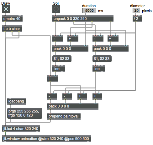
Here’s a simple demonstration of that idea. A purple circle will seem to move diagonally from the left-top corner of the window to the right-bottom corner because its x and y coordinates are being changed constantly according to a linear trajectory.

animate an object by linear repositioning

Before writing the program, I made the decision that I wanted it to move a purple dot diagonally across the full size of the window from coordinate 0,0 to coordinate 320,240. In a more sophisticated program, it would be nice if the object could be moved from any point to any other point; but for simplicity, I decided this program would have just one move it knew how to do. So I typed those coordinates into a single object, unpack, which takes items of a list and sends them out individual outlets in right-to-left order. In order to demonstrate how to have some variable possibilities in a program, though, I made it so that the speed and size of the dot could easily be altered.

This sort of automated animation of graphics requires a bit of arithmetic calculation to construct messages that have the right arguments. I decided that the line objects should provide the horizontal and vertical coordinates for the center of the circle, and the program would calculate all the necessary coordinates for the bounding square that would tell jit.lcd where to paint it. The diameter of the circle is specified by a live.numbox, which sends out the number 20 initially, and is limited between 2 and 80. The duration of the trajectory for the two line objects is specified by the other live.numbox; it’s 5000 ms by default, and is limited between 500 and 20000.

When the patch is loaded, the duration value 5000 is stored in the right inlet of the pack objects, and the diameter value 20 is divided by 2 to get the radius and then is stored in the right inlet of all the + and objects. Also, the loadbang object sets the background color to white (not really necessary, since that’s the default color for jit.lcd anyway) and the foreground color (i.e., the pen color) to purple. When you turn on the toggle labeled “Draw”, at first you won’t see anything happen because the jit.lcd object will receive the message ‘paintoval 0 0 0 0’, which draws an infinitely small oval.

When you click the the button labeled “Go”, it constructs messages to the line objects telling them, “Start at a point that’s radius pixels above and to the left of the window (just outside the left-top corner of the visible window area) and go to a point that’s radius pixels below and to the right of the window (just outside the right-bottom corner of the visible area) in duration milliseconds.” The line objects each send out a number once every 10 ms, and those numbers serve as the horizontal and vertical coordinates of the center point of the circle at each instant. Those coordinates have the radius value subtracted from them or added to them to determine the coordinates of the left-top and right-bottom corners of the bounding square, and those four numbers are combined into a four-item list in a pack object.

There’s one more important little trick, though. The output of the line object on the left doesn’t go directly to the pack object. It’s stored in an int (i) object, and only gets sent out when the i object receives a ‘bang’. Every time the qmetro sends a ‘bang’, we first use it to erase (‘clear’) the previously drawn object, then we trigger the i object which triggers the left inlet of the pack object which causes a ‘paintoval’ message to be constructed and sent to jit.lcd, then finally we send the ‘bang’ to trigger the jit.lcd object to send the new image to jit.window. If you think logically and procedurally about the ordering of these steps, you’ll realize the method by which you can a) erase the previous drawing, b) calculate, construct, and send the messages that will provide the drawing instructions, and then finally, c) send out the matrix.

Draw shapes and text

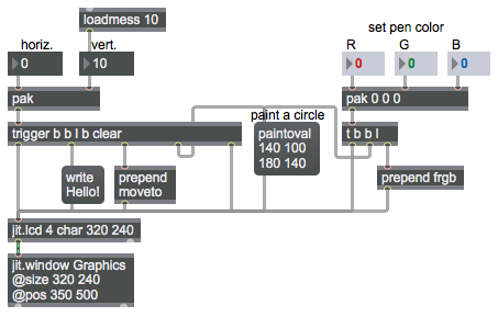
The jit.lcd object understands a variety of command messages for drawing simple things such as lines, geometric shapes, text, and pictures any place in a matrix. You can think of the matrix in jit.lcd as a canvas on which you can draw, write, or paint using messages. You choose a color “pen” you want to use, you move the cursor to the location where you want to draw something, then you draw it. This patch demonstrates a few of the many drawing messages you can send to jit.lcd.

draw shapes and text

The message ‘frgb’ sets the pen color using three arguments for intensity of red, green, and blue. For example ‘frgb 255 255 0’ mixes full intensity red and green to get yellow, and ‘frgb 128 0 128’ mixes red and blue to get purple. Initially, the pen color is black (0 0 0) by default. By default the background color used for every undrawn pixel is white (255 255 255), but you can change the background color with the ‘brgb’ message (not shown in this patch). For example, ‘brgb 192 192 192’ would make the background light gray.

In the example patch, we use the pak object to collect the three color arguments as a list, and then we use the prepend object to put the word ‘frgb’ before the list to construct a complete message for jit.lcd. The pak object is similar to the pack object, but a message in any of pak‘s inlets triggers output, whereas only a message in the left inlet of pack triggers output. Since we’re using pak, a new ‘frgb’ message will be triggered whenever you change any of the three color arguments.

The ‘paintoval’ message paints a filled oval using the pen color specified by the most recent ‘frgb’ message. You specify the location of the oval in the four arguments of the ‘paintoval’ message, which designate the left, top, right, and bottom coordinates of the rectangle that bounds the oval you want to paint. In this example the bounding rectangle’s left-top corner is at coordinate 140, 100 (140 pixels from the left edge and 100 pixels from the top edge) and its right-bottom corner is at 180 140, resulting in a circle with diameter of 40 pixels.

To draw lines or write text, you first have to move the cursor to the desired drawing location with a ‘moveto’ message, then give the drawing command. The normal thing to do is to send all the drawing messages that are needed to draw whatever you want to draw, then use a ‘bang’ to send out the completed matrix. The upper left portion of the patch shows how a number of messages can be triggered instantaneously (in rapid succession) to do all the different steps in making the drawing.

Whenever you change one of the number boxes marked “horiz.” or “vert.” to change the location of the written text, pak object combines both coordinates into a single two-item list, and the trigger object (which can be abbreviated as t) then causes five things to happen: it clears the matrix in jit.lcd (fills it with the background color), paints the oval, moves the cursor to the specified coordinates, writes the text “Hello!” there, then sends the matrix to .jit.window to be displayed.

Assignment for February 24, 2015

In the Max 7 Documentation, read MSP Sampling Tutorial 1: Record and Play Samples and MSP Sampling Tutorial 3:  Sample Playback with Loops. (Note that these links are all to the web documentation. You can read the same material in the Max Documentation that’s accessible in the Help file of the Max application, with the added benefit of being able to open and try the example patch.)

The buffer~ object discussed in those two tutorials is key to many types of sample manipulation in MSP. A buffer~ creates a place in the computer’s random access memory (RAM) to store audio. Audio in RAM is more quickly accessible than sound that is read from the hard disk, and is accessible at any “random” location within the audio buffer. Whereas with sfplay~ you can open and read a file from the hard disk (and indeed sfplay~ preloads a few milliseconds of the sound into RAM as a buffer in order to stay ahead of where it’s reading), with buffer~ you can preload any amount of sound you’d like into RAM (up to the limit of your computer’s available memory) and thus your program can access any place in the sound instantaneously.

Every buffer~ object must have a unique name typed in as an argument, and other MSP objects can then access the sound that’s in that place in memory simply by referring to the buffer name.

Study examples 15-21 from the 2012 class, and try out the patches. Post any questions you have about any of these tutorials and examples on the Q&A site.

You should now be well underway with your programming project. If you haven’t yet written out the detailed version of your project plan, as described in the Assignment for February 12, 2015, you should do so immediately and begin programming as soon as possible. Post thoughts, ideas, discoveries, etc. on your blog as you go (think of it as the ongoing notepad and journal for your project), and post questions to the Q&A site.